| |
You are here: < RX I.F. Mods > Kenwood TS-850S RX I.F. Board Modifications:
As with the DSP-100 TX mod, if you are a purist and want the fullest and flattest receiver response possible with the 850/DSP-100 combination for SSB, you will want to perform this modification which enables the receiver to respond flat from 20hz to 6kHz, including speaker, headphone, and ACC2 outputs. 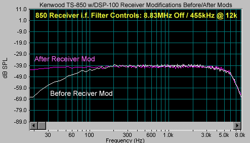 Kenwood TS-850S i.f. Board Flat Frequency Response Modifications Instructions:
If you will be performing the direct Balanced Modulator feed for AM, leave the I.F. board out and see the "AM MODS" page. Otherwise, you can now reinsert the I.F. board, replace the screws, connectors and bottom cover. 455 kHz I.F. RECEIVER FILTER MODS: If you would like the widest receiver bandwidth possible, (RX and TX on AM) there are two methods of doing this: - Place a jumper wire from pin 2 to pin 2 of the optional 455 kHz 500 Hz filter pins. (Photo 21) Or: - Install a Murada 20kHz filter on an Inrad/850 filter adapter board and install in the 455 kHz 500 Hz filter position. (Photo 22) Make sure that you enable the 455 kHz I.F. 500 Hz position by setting the top panel dip switches appropriately. These 455 kHz filter mods dramatically improve the receiver frequency response on SSB and AM but is most useful on AM. Additionally, you can transmit through this filter position on AM when using the direct balanced modulator feed. When using the DSP-100 with SSB, the 455kHz I.F. filter is not active, since the DSP-100 does all 455 kHz I.F. processing.
|
||||||||||||||||||||||||||||||||||||||||||||||||||||||||||||
|---|---|---|---|---|---|---|---|---|---|---|---|---|---|---|---|---|---|---|---|---|---|---|---|---|---|---|---|---|---|---|---|---|---|---|---|---|---|---|---|---|---|---|---|---|---|---|---|---|---|---|---|---|---|---|---|---|---|---|---|---|---|
| |
|||||||||||||||||||||||||||||||||||||||||||||||||||||||||||||
| |
Copyright © 2024 KA0KA | ||||||||||||||||||||||||||||||||||||||||||||||||||||||||||||
| Home | About KA0KA | RX Mods
| DSP-100 Mods | AM Mods | 850 Setup |
|||||||||||||||||||||||||||||||||||||||||||||||||||||||||||||