KA0KA - The Kenwood TS-850/DSP-100 Project Home Page


You are here: < AM Mods >

850 Balanced Modulator Feed to I.F. Board
Kenwood TS-850S AM Modifications:

The Kenwood TS-850S is capable of some beautiful Low-level, solid state AM modulation if set up properly. There are a few things to consider when using the 850 for AM...

You could simply plug a microphone into the 850's mic input and set the 455 kHz i.f TX filter at 12k and sound okay. But the 850 is capable of so much more quality than can be achieved with the method just mentioned.

First, I recommend a good quality microphone that is capable of reproducing at least 50 Hz ~ 15 kHz
Secondly, some external audio processing can really help shape the AM audio response.

When the mods are complete, you should have no trouble attaining a flat 10kHz AM audio frequency response!


1)

Balanced Modulator input:

  • Place the 850 upside-down and remove all the screws on the bottom and sides of the case.
  • Remove the bottom cover.
  • Locate the I.F. board (X48-3080-00) This is the board that has the RTTY RCA jack mounted to it.
  • Remove all Molex connectors and Ribbon Cables from this board.
  • Remove all screws and carefully remove the board.

Locate IC3 (It's a 7 pin single in-line IC) Pin 1 is located at the "Beveled" side of the IC chip.
Solder the RG-174 cable's center and shield to the foil side of the board as follows:
Plus (Center of RG-174 Teflon RF Cable) to IC3, Pin 1 on bottom of IF board.
Minus (Shield of RG-174 Teflon RF Cable) to IC3, Pin 4 on bottom of IF board.
(See Photo 5)

Feed the cable from IC3 under the chassis through a corner hole of chassis to the top front left side.
There is a square hole that is clear, from the bottom to top of the chassis.

Coax Cable connections on the top front left side to interface the RTTY RCA rear panel jack:
We need to disconnect the RTTY circuit and replace it with the Line level audio from your rack to the balanced modulator inputs performed above.

  (See Photo 6 for illustration to the below instructions)
2) Orient the 850 so that the back is facing you.
3) Locate the small board on the top right side of rear chassis.
(This board mounts the RTTY, DSP 1 & DSP 2 RCA jacks)
4) Remove the 2-wire (2-pin) green Molex connector. (White and Black wires)
5) Remove the 1-pin (Orange) connector to the left of the 3-pin Molex connector.
6) Solder the minus side of a 4.7uF Axial electrolytic (Vishay Part# 594-2222-021-38478) Electrolytic capacitor to the 1 pin on the mini board.
7) Solder the Plus side of the 4.7uF Axial electrolytic Vishay (Part# 594-2222-021-38478) to the center of the RG-174 cable. (This comes from IC4 pin 1 of the balanced modulator).
8) Solder the shield of the RG-174 to the far right pin (toward the outside of the chassis)
of the 2 pin Molex connector that was there. (Where the Black wire was)
(This comes from pin 4 of the IC3 balanced modulator and is signal ground).
 

For coupling between the air-chain and transmitters balanced modulator, I recommend the Radial JDI MK3 Passive Direct Box, this marvel employs the Jensen JT-DBE transformer as its main drive engine and provides complete isolation and reduced noise. The exceptionally low phase distortion, almost perfect linear response, and low harmonic distortion make the JDI direct box a superb choice for high R.F.I. environments.

Radial JDI MK3 Passive Direct Box

Jensen Transformer JT-DBE
-15dB pad
Ground Lift
180 degree phase invert


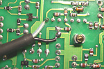
455 kHz I.F. RECEIVER FILTER MODS:
If you would like the widest receiver bandwidth possible, (RX and TX on AM) there are two methods of doing this:

- Place a jumper wire from pin 2 to pin 2 of the optional 455 kHz 500 Hz filter pins. (Photo 21)
Or:
- Install a Murada 20kHz filter on an Inrad/850 filter adapter board and install in the 455 kHz 500 Hz filter position. (Photo 22)

Make sure that you enable the 455 kHz I.F. 500 Hz position by setting the top panel dip switches appropriately.

These 455 kHz filter mods dramatically improve the receiver frequency response on SSB and AM but is most useful on AM.
Additionally, you can transmit through this filter position on AM when using the direct balanced modulator feed.
When using the DSP-100 with SSB, the 455kHz I.F. filter is not active, since the DSP-100 does all 455 kHz I.F. processing.

Make sure to performe the TX bandwidth selection menu as seen in the 850 setup page.


Copyright © 2024 KA0KA